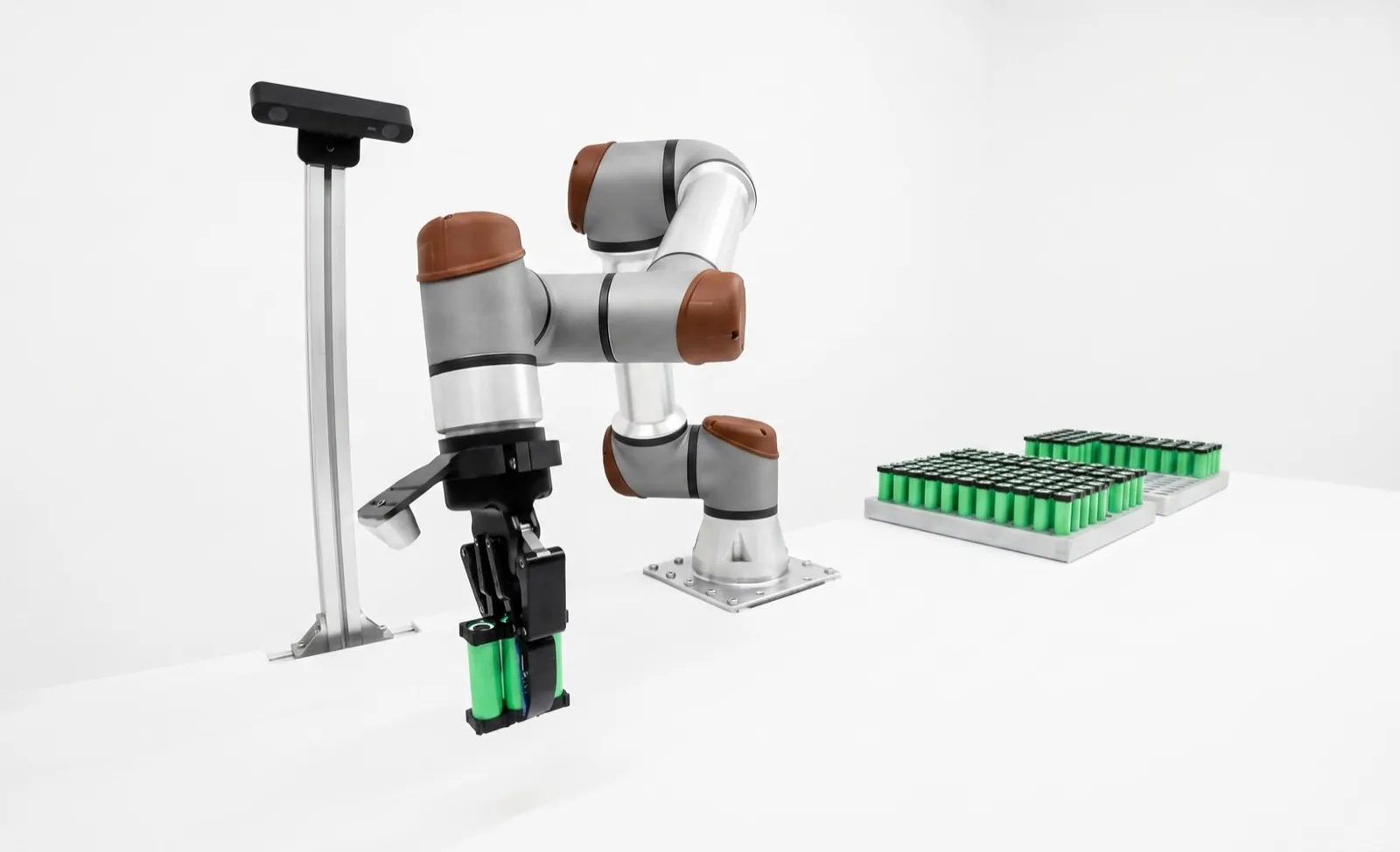
2D vs 3D machine vision: when you actually need depth.
A 2D camera measures brightness, so it sees outlines, print and contrast. A 3D sensor measures distance, so it sees height, volume and tilt whatever the color. Most inspection is 2D work. You need 3D when the answer's a height, or when the feature has shape but no contrast.
On this page
Use 2D machine vision when the decision lives in the image plane, like presence, position, outline dimensions, codes, print and most cosmetic defects. Use 3D when it's a height, depth, volume, flatness or tilt, or when a robot has to pick parts whose height varies. 3D costs more, so buy it for a specific measurement.
We put both kinds into our cells, and we see the same mistake in both directions. One team spends months fighting a 2D station to infer a height it can't see. Another buys a 3D sensor for a job a well-lit 2D camera would've done faster and cheaper. If you're already shopping for hardware, our 3D vision camera guide compares the cameras. This post is about whether you need one.
Key takeaways
- 2D measures brightness. It's great at presence, outlines, codes, color and most cosmetic defects, and it can't measure height.
- 3D measures distance. You need it for height, volume, flatness, coplanarity, bead profile and bin picking.
- Laser profilers are the most precise but need motion. Structured light gives dense point clouds of a still scene, and time of flight is fast but coarse.
- Every 3D sensor has roughly 2,000 to 3,200 points across its view, so a bigger field of view always means coarser data.
- Write the tolerance down first. A number on the drawing tells you whether you need 3D.
What's the difference between 2D and 3D machine vision?
A 2D vision system records how much light comes back from each point, so it measures what shows up as contrast, like edges, outlines, print and color. A 3D system records distance to each point, so it measures height, depth, volume and orientation directly, even when there's no contrast at all. That's the whole distinction.
2D cameras are cheaper and simpler, and they cover most of the inspection we see. 3D sensors produce a height map or point cloud, which costs more to buy and to process. So the honest question isn't "is 3D better?" It's whether the thing you're deciding is a distance.
What can a 2D vision system measure?
A 2D vision system measures anything that shows up as a pattern of brightness in the image plane. That covers presence and position, outline dimensions, codes and characters, color, and most cosmetic defects such as scratches and stains. With a backlight and a telecentric lens, it'll gauge outlines to a small fraction of a pixel.
Those jobs line up with most of our vision library.
- Presence, absence and position of clips, labels and fasteners, covered in assembly verification with machine vision.
- Outline dimensions like hole diameters, edge positions and gaps, covered in dimensional gauging with machine vision.
- Codes and characters, covered in OCR and code reading.
- Color and cosmetic flaws, which are changes in reflectance rather than shape, covered in surface defect inspection.
Resolution's easy to reason about. A 5 MP sensor that's 2,448 pixels wide, imaging a 100 mm field, gives 100 / 2,448 = 0.041 mm per pixel, and subpixel edge tools can place a high-contrast edge to a fraction of that. The machine vision resolution calculator does that math for your tolerance, and our post on machine vision camera resolution explains why the rule of thumb isn't one pixel per tolerance.
Can 2D machine vision measure height?
Not directly. A 2D camera only sees height when it happens to change the brightness, through a shadow, a side view or a change in focus. Those tricks tell you something sticks up. They can't give a calibrated height across the part, so if height has a tolerance, you'll need 3D.
Here's the arithmetic for a pin standing 0.3 mm proud, seen by a standard lens from 300 mm away. The pin top is 0.3 / 300 = 0.1% closer, so its image is about 0.1% bigger. On a 10 mm pin that's 0.01 mm, or a quarter of a pixel at the resolution above, and part position tolerance swamps it. The camera simply can't tell a flush pin from a proud one, which is what Fig. 01 shows.
There are workarounds. Low-angle light makes a raised edge cast a shadow, and photometric stereo recovers surface relief from images lit from several directions.10 They're good for "is something sticking up?" They aren't a height gage.
How does 3D machine vision work?
Industrial 3D machine vision gets depth in four main ways. Laser triangulation, structured light and stereo all view the scene from two positions a known distance apart and work out depth from the geometry. Time of flight measures how long light takes to come back. Each one's a different trade between range, resolution and speed.
Laser triangulation profilers
A laser profiler projects a thin laser line onto the part and watches it with a camera set at an angle. Where the surface rises, the line shifts sideways in the image, in proportion to the height change. Each frame's one profile across the line. Move the part under the sensor, with an encoder counting the travel, and the profiles stack into a height map.
Profilers are the precision end of 3D, and one product family shows the whole range. In Keyence's LJ-X8000 series, the shortest-range head covers a line about 7.5 mm wide with 2.5 µm point spacing and 0.3 µm Z repeatability. The longest-range head covers about 510 mm with 225 µm spacing and 10 µm repeatability, and every head returns 3,200 points per profile.1 SICK's Ranger3 uses laser triangulation at up to 1,500 full-frame profiles per second, or 20,000 in a reduced region.2 LMI's Gocator line profilers and Cognex's L68 series laser displacement sensors sit in the same category.34
The catches are real, though. Something's got to move, smoothly and measurably. Shiny and very dark surfaces send back weak or misleading reflections. And the laser needs a safety assessment, since Keyence rates its LJ-X8000 heads Class 2M or Class 3R depending on model.1
Structured light 3D cameras
A structured-light camera swaps the laser line for a projector that throws stripes or codes over the whole scene, and a camera at a known offset works out how they bend over the surface.8 You get a dense point cloud of the whole field in one capture, which is why it's the default for bin picking.
Two published examples show the scale. Zivid lists the Zivid 2+ M60 with a 30 to 110 cm working distance and a 58 × 47 cm field of view with 240 µm spatial resolution at 60 cm.6 Photoneo's PhoXi range runs from the S (a 360 × 272 mm area at its sweet spot, 0.174 mm point spacing, 0.05 mm temporal noise, 230 mm baseline) to the XL (1,954 × 1,459 mm, 0.947 mm spacing, 0.4 mm noise, 850 mm baseline), with scan times from 250 ms up to 2.25 s and 3 s.5 Notice what grows with the scene. Baseline, point spacing and noise all go up together.
The catches here are capture time (the scene has to hold still), ambient light and shiny parts. If you're choosing between the two big names, see Zivid vs Photoneo.
Stereo vision
Stereo uses two cameras a known distance apart and finds the same point in both images. The offset between them, the disparity, gives the distance. Passive stereo needs texture to match, and active stereo projects a random pattern so it works on plain surfaces. It captures in one shot and doesn't mind ambient light, which suits moving scenes.
Its weak spot is distance. Depth is z = f · b / d (focal length times baseline over disparity), so a fixed disparity error gives a depth error that grows with the square of distance, δz ≈ z² · δd / (f · b).10 Double the working distance and the depth error roughly quadruples. That's why long-range stereo heads keep getting wider.
Time of flight cameras
A time-of-flight camera floods the scene with modulated infrared light and measures, per pixel, how long it takes to come back. There's no baseline and no motion, so it's compact and fast and covers big scenes. The cost is resolution. Basler's blaze-101 is a 640 × 480 sensor with a 67° × 51° field of view, a working range up to 10 m and typical accuracy of ±5 mm between 0.5 and 5.5 m, at up to 30 frames per second.7 That's excellent for finding boxes on a pallet. It's the wrong tool for a 0.1 mm tolerance, and multipath reflections in corners can distort it too.
| Method | How it gets depth | Motion needed? | Best at | Watch out for | Examples (verified) |
|---|---|---|---|---|---|
| Laser profiler | Laser line viewed at an angle | Yes, part or sensor moves | Micron-level height on moving parts | Occlusion, shiny or dark surfaces, laser safety | Keyence LJ-X8000, SICK Ranger3, LMI Gocator, Cognex L68 |
| Structured light | Projected patterns viewed at an offset | No, but the scene holds still | Dense sub-mm point clouds, bin picking | Capture time, ambient light, reflections | Zivid 2+, Photoneo PhoXi |
| Stereo | Disparity between two cameras | No, single shot | Moving scenes, ambient light, large areas | Needs texture or a projector, error grows with z² | Many vendors, check per model |
| Time of flight | Round-trip time of modulated light | No, video rate | Fast, wide, coarse depth | Millimeter-class accuracy, multipath | Basler blaze-101 |
Which 3D vision technology is most accurate?
On a small field of view, laser profilers are the most precise, with Keyence listing 0.3 µm Z repeatability on its shortest-range head. Structured light comes next and covers far more area per shot, and time of flight's the coarsest. Accuracy is tied to field of view, so compare sensors at your size.
Every 3D vision camera's got a fixed number of points across its view, so a bigger view means wider spacing and, almost always, more noise. When we plotted the published specs from the products above, they landed in a surprisingly tight band of about 2,000 to 3,200 points across, whatever the technology. Time of flight is the outlier at 640.
So if you need fine resolution over a big part, you'll scan it with a profiler on a robot or use several sensors. Ask every vendor for specs at your working distance, too. Repeatability on a matte white lab target isn't repeatability on your anodized, curved part. And structured light vs time of flight is rarely a close call once the field of view and tolerance are written down.
When do you need 3D vision inspection?
You need 3D vision inspection when the pass or fail decision is a distance. That's height, step, volume, flatness, coplanarity, bead profile or flush, or a robot picking parts whose height and tilt vary. You may also need it when a defect has shape but no contrast, like a dent in a uniform part.
On the stations we've scoped, the jobs that really need depth fall into six groups.
- Height and step, like pin protrusion, press-fit depth, connector seating or a lifted gasket.
- Volume, like dispensed adhesive, sealant and thermal paste, food portions and fill levels. Volume is height summed over an area, so it needs a height map.
- Coplanarity and flatness. JEDEC's JESD22-B108B test measures how far package terminals deviate from coplanarity, which is a 3D measurement by definition.9 Warped molded or machined parts belong here too.
- Bead profile, meaning the width, height, cross-section and position of adhesive beads and welds. See bead and dispense inspection and weld inspection with machine vision.
- Bin picking and depalletizing, where the robot needs each part's height and tilt. See our robotic bin picking cells and the vision-guided robotics guide.
- Flush and gap. Gap shows up in 2D. Flush, one surface standing proud of the next, is a height.
There's a seventh case that's really about contrast. Dents in uniform parts, black rubber on black plastic, a defect the same color as the background. If no light gives you reliable contrast, 3D may be the dependable way to see shape. Test first, though, because the right technique from our machine vision lighting guide often fixes it in 2D. We'd much rather sell you a ring light than a 3D sensor you didn't need.
Where 2D still wins, even beside a 3D sensor
Codes, print, color and most cosmetic defects are reflectance problems, and a 3D sensor's the wrong tool for them. Plenty of our 3D stations also carry a 2D camera, or use the 3D sensor's own intensity image, for exactly that reason. Deburr and edge inspection often splits the same way.
Is 3D vision more expensive than 2D?
Yes, and usually by more than the sensor price gap suggests. A 3D station often adds controlled motion with an encoder, a stiffer mount, calibration to the robot or conveyor, heavier compute and a laser safety review. The total depends on the job, so it's worth pricing a specific station.
The sensor's only one line that grows. A profiler might need a linear axis or a robot pass, plus the cycle time that pass eats. Micron-level height measurement is also micron-level vibration measurement, so mounts get heavier. 3D tools are less standardized than 2D toolsets, so you'll spend more engineering hours. And fewer technicians are fluent in 3D, which matters the day something drifts after handover.
We don't quote a rule of thumb for the premium because it swings so much with the application. Our post on machine vision system cost breaks down the line items, and machine vision ROI shows how to weigh them against escapes and labor.
Is 3D vision slower than 2D?
Often, yes. 3D data is bigger, so there's more to move and process, and structured-light cameras typically need hundreds of milliseconds per capture. Laser profilers are fast per profile but need the part to travel past them. Time of flight runs at video rate and gives up resolution to do it.
Some arithmetic on the published numbers makes the size difference concrete.
- A 5 MP monochrome 2D image at 8 bits per pixel is about 5 MB.
- A structured-light scan of up to 3.2 million points (Photoneo's PhoXi figure), stored as three 32-bit coordinates per point, is 3.2 M × 12 bytes ≈ 38 MB before color.5
- A profiler at 3,200 points per profile and 16,000 profiles per second (Keyence's top rate for LJ-X8000 heads in 3D mode, with a narrowed range) makes 51.2 million heights a second, roughly 100 MB/s at 2 bytes each.1
The processing changes in kind, too. 3D tools fit planes, measure height from a datum and match CAD models for pose. The station has to find that datum reliably before it measures anything, and that's where a lot of commissioning time goes. Rule-based geometry still does most industrial 3D measurement, for reasons we cover in machine vision vs computer vision.
2D vs 3D machine vision: how do you decide?
Work down Fig. 04 and stop at the first yes. If the answer's a height, depth, volume or flatness, use 3D measurement. If the part's pose varies in height or tilt, use 3D guidance. If the feature is shape without contrast, test both. Otherwise a well-lit 2D camera will usually do the job.
Three habits make the call stick. Write the measurement down with a tolerance first ("pin height 1.20 ± 0.10 mm above the datum face"), because that tells you right away whether you need 3D. Test on real production parts, ugliest finishes included. And get the sensor's specs at your working distance, then check them with a gage study before acceptance, as we lay out in how to validate a vision inspection station.
Still at the "should we even automate this?" stage? Start with starting your first machine vision project. And if you'd like a second opinion on a specific station, it's the kind of question we work through on our machine vision integration projects all the time.
Frequently asked questions
Can you combine 2D and 3D vision in one station?
Yes, and we often do. Many 3D sensors also return a 2D intensity image, and some stations add a separate 2D camera. The usual split is 3D for height, volume or pose and 2D for codes, print, color and cosmetic defects. Just make sure both views are calibrated to the same part coordinates, or the results won't line up.
Does 3D vision work on shiny or reflective parts?
It can, but shiny parts are the hardest case for every 3D method. Mirror-like surfaces bounce the laser or projected pattern away from the camera, or straight into it as glare, which leaves holes or false points. Fixes include changing the sensor angle, HDR capture modes or a different technology. Always test with your real parts, and don't skip the shiniest ones.
What is a 3D point cloud?
A point cloud is a list of 3D points, each with X, Y and Z coordinates, that together describe the surfaces a sensor saw. Structured-light, stereo and time-of-flight cameras produce one per capture. Laser profilers usually produce a height map instead, which is a grid of Z values over X and Y, and that's often easier to process for inspection.
How far away can a 3D vision camera work?
It depends on the technology and the model. Short-range laser profiler heads sit very close, and Keyence's shortest-range LJ-X8000 head has a 20 mm reference distance. Structured-light cameras like the Zivid 2+ M60 work from 30 to 110 cm, Photoneo's PhoXi XL scans out to about 3.8 m, and time-of-flight cameras such as Basler's blaze-101 reach 10 m.
Do 3D vision cameras need calibration?
Yes, in two senses. The sensor is factory-calibrated so its depth values are right, though it's worth checking against a known artifact on site. Then it has to be calibrated to your world, with a hand-eye calibration to the robot or a mapping to the conveyor and part datum. That second step is a commissioning task, and you'll redo it if the mount moves.
Is 3D vision only for robots and bin picking?
No. Robot guidance is the most visible use, but a lot of 3D vision is pure inspection, like adhesive bead volume, weld profile, connector coplanarity, pin height and flush on assembled housings. Laser profilers mounted over conveyors do this on parts moving at line speed, and there's no robot involved at all.
Sources
- Keyence, 2D/3D Laser Profiler LJ-X8000 series: specifications. Head measurement ranges, profile data interval, 3,200 points per profile, Z-axis repeatability, laser class, and controller sampling up to 16 kHz in 3D mode with a narrowed range. Accessed October 2026. Read the specifications.
- SICK, Ranger3 V3DR3-30NE31111 datasheet. Measurement principle listed as 3D laser triangulation; 1,500 full-format and 20,000 region-of-interest profiles per second for the V3DR3-30NE31111. Accessed October 2026. Read the datasheet (PDF).
- LMI Technologies, Gocator 3D smart sensors, product family overview listing laser line profile sensors, snapshot sensors and line confocal sensors. Accessed October 2026. Read the LMI page.
- Cognex, 3D Machine Vision Systems, product overview including In-Sight L38 series, L68 series 3D laser displacement sensors and 3D-A5000 area scan cameras. Accessed October 2026. Read the Cognex page.
- Photoneo, PhoXi 3D Scanner S and PhoXi 3D Scanner XL datasheet tables: scanning area, point-to-point distance, temporal noise, baseline, scanning time and up to 3.2 million 3D points. Accessed October 2026. PhoXi S and PhoXi XL.
- Zivid, Zivid 2+ M60 product page: 30 to 110 cm working distance, 58 × 47 cm field of view and 240 µm spatial resolution at 60 cm. Accessed October 2026. Read the Zivid page.
- Basler, blaze-101 documentation: 640 × 480 resolution, 67° × 51° field of view, working range up to 10 m, typical accuracy ±5 mm from 0.5 to 5.5 m, 20 to 30 fps. Accessed October 2026. Read the Basler documentation.
- Jason Geng, Structured-light 3D surface imaging: a tutorial, Advances in Optics and Photonics 3, 128 to 160, 2011. Read the paper.
- JEDEC, JESD22-B108B: Coplanarity test for surface-mount semiconductor devices, published September 2010, reaffirmed February 2023. Read the JEDEC listing.
- Richard Szeliski, Computer Vision: Algorithms and Applications, 2nd edition, Springer, 2022. Chapters on stereo correspondence, depth estimation and photometric stereo. Book site.
Product specifications are taken from each vendor's published pages as cited and accessed in October 2026. Vendors revise models often, so confirm the current datasheet for your variant. The ToF point spacing, data sizes and profile-rate figures are our arithmetic from those specs, shown in the text. Fig. 01 uses an illustrative part and values. The guidance on which applications need 3D, the cost drivers and the decision tree come from our applications engineering experience, not from a survey.
Read next
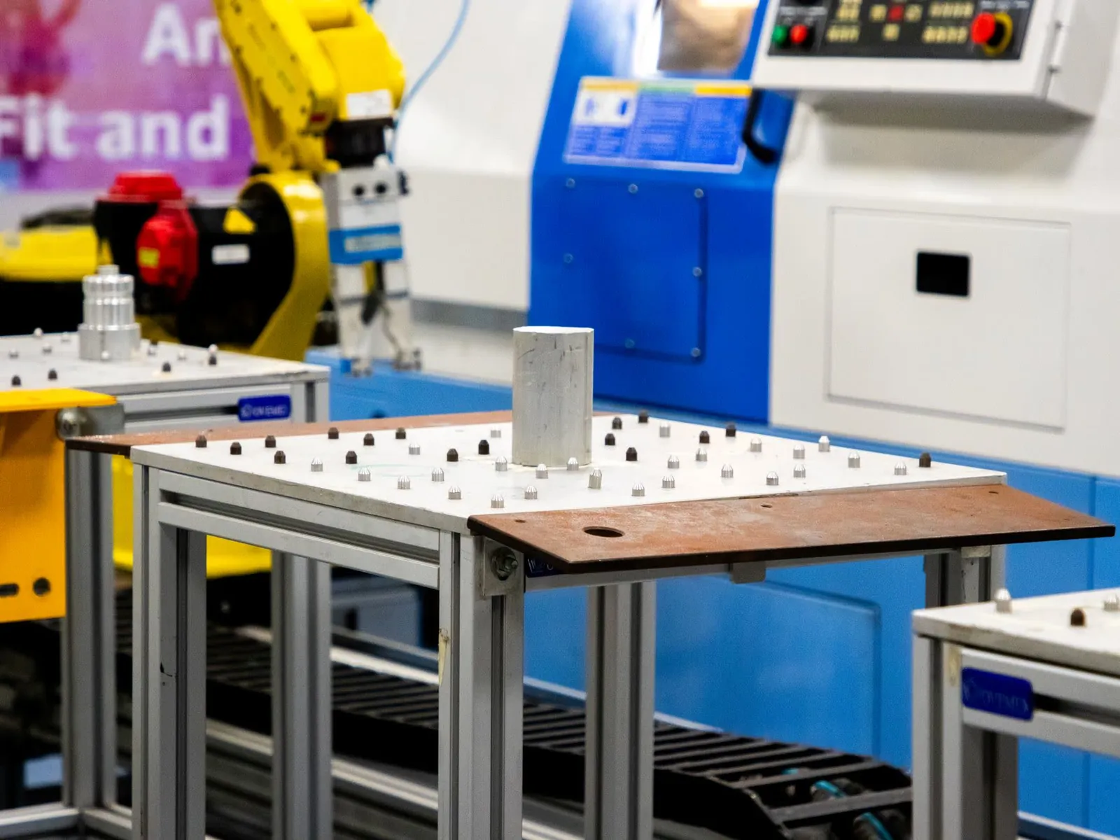 Robot guide
Best 3D vision cameras for bin picking
Structured light, time of flight and stereo cameras compared for picking cells.
Robot guides↗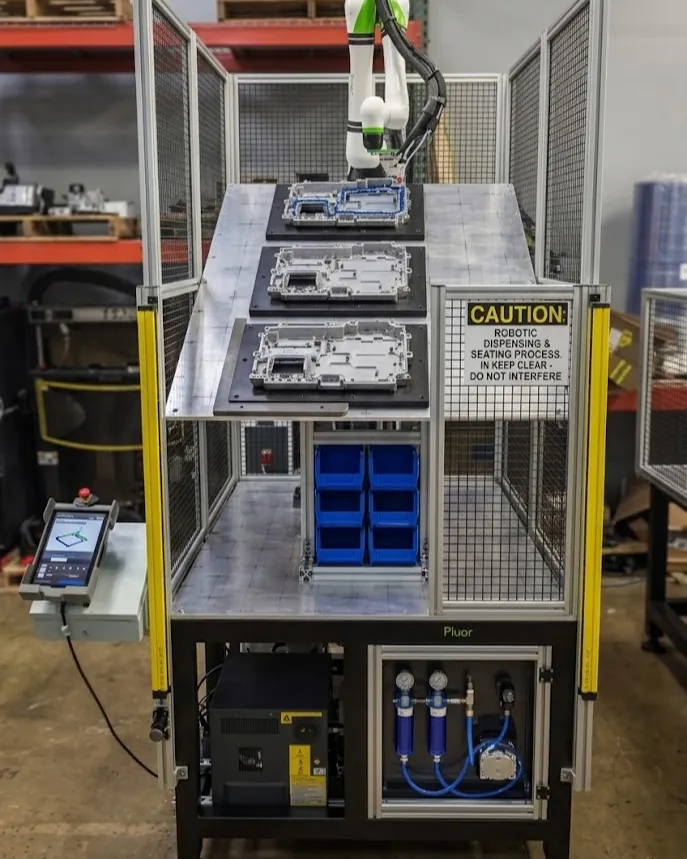 Vision guide
Bead and dispense inspection
Measuring bead width, height and volume in 3D, and where 2D is enough.
Machine vision library↗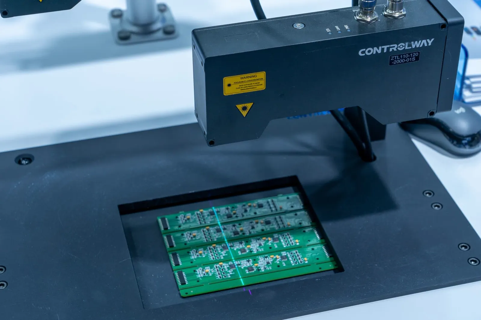 Machine vision
 camera resolution
How many pixels a tolerance really needs, worked through with examples.
Buyer series↗Find out whether your station needs 3D.Bring Relling to your shop floor.
We started Relling to help American manufacturers make more of what this country needs. Tell us about the part and we'll scope a cell to it.