Locate on a flat table or tray
What it solves: parts loose on a plane at known height. The camera reports x, y and rotation; the robot comes down to a fixed z. Watch for: touching or overlapping parts. Reject them and re-spread.
A camera that finds a part is half a system. The other half is the math that turns a pixel into a robot target, the calibration that makes it true, and the timing that keeps it true on a moving belt. Here's all of it, with the error and cycle budgets we use when commissioning a cell.
Use 2D when parts lie flat on a known plane, 2.5D when they sit level at varying heights, and 3D when they tilt, stack or pile. Mount the camera fixed when cycle time matters and on the wrist when you need angles or close-up resolution.
Accuracy comes from the chain, not the camera. Calibrate where the robot actually works, latch the encoder at the exposure on moving belts, and budget camera, robot, pose and gripper errors together. Vision can retire a precision locating fixture. It can't retire a clamp the process needs.
The first question isn't which camera. It's how many degrees of freedom the part has when the robot reaches it: three lying flat (x, y, rotation), six in a bin. Every step up costs sensor money, compute time and calibration effort.
What it solves: parts loose on a plane at known height. The camera reports x, y and rotation; the robot comes down to a fixed z. Watch for: touching or overlapping parts. Reject them and re-spread.
What it solves: random orientation on a belt that never stops. The camera locates upstream; the robot tracks the belt with an encoder. Watch for: trigger jitter, which becomes millimeters at belt speed (section 05).
What it solves: parts that stay level at different heights. A height map tells the robot which layer is on top and how far to reach. Watch for: shrink wrap, labels and seams that look like box edges in 2D.
What it solves: parts piled at any angle in a tote. A 3D camera returns a point cloud, software fits part models, and a planner picks a reachable, collision-free grasp. Watch for: the last parts, lying against walls and corners.
What it solves: loading a chuck, nest or press whose position varies a little between cycles. A wrist camera images a datum and corrects the taught place point. Watch for: image from the same pose every time.
What it solves: parts that shift when the gripper closes. The robot passes over an upward-facing camera and corrects the place pose by the measured offset. Watch for: motion blur. Strobe it.
The camera reports where the part is relative to the camera. The robot needs to know where the part is relative to its base. Everything in between is bookkeeping, and every link in the bookkeeping has its own error.
Each arrow is a rigid transform (a rotation plus a translation, usually a 4×4 matrix), and expressing the part in robot coordinates means multiplying the chain. For a fixed camera that's base→camera (the hand-eye result) times camera→part (the vision result), times the grip offset. The controller then solves the joint angles that put the TCP there.
Two consequences. The TCP matters as much as the camera: a tool frame 1 mm off is a 1 mm miss on every pick, and a rotated one turns rotation corrections into position errors. And 2D quietly assumes a plane. Parts higher or lower than the calibrated plane appear shifted to a camera looking at an angle, which is why 2D VGR wants a camera looking straight down and parts of consistent height.
The major robot makers build the chain into the controller so that vision results arrive as offsets to a user frame. FANUC iRVision runs inside the robot controller, calibrates cameras with a dot-grid plate, and offers grid-based utilities to set user and tool frames. ABB Integrated Vision pairs the IRC5 controller and RobotStudio with Cognex In-Sight smart cameras, and its PickMaster software adds vision-guided conveyor picking. Smart-camera vendors work from the other side: Cognex In-Sight offers hand-eye calibration routines for fixed and robot-mounted cameras plus a Sequential N-Point tool, and Keyence sells a 3D vision-guided robotics system (CV-X480D) with automatic robot-camera calibration and built-in path planning.
A fixed camera and a wrist camera solve the same equation with a different unknown. The choice changes cycle time, resolution, cabling and what you have to recalibrate when someone bumps something.
| Factor | Eye-to-hand (fixed) | Eye-in-hand (wrist) |
|---|---|---|
| Calibrated unknown | Camera relative to robot base | Camera relative to the flange |
| Cycle time | Imaging overlaps robot motion if the arm clears the view | Adds an imaging stop or slowdown each cycle |
| Resolution | Set by the whole pick area. A 600 mm field on a 2,448-pixel sensor is about 0.25 mm/px | Can image a 100 mm field from close in, about 0.04 mm/px on the same sensor |
| Error sources | Bracket drift, thermal growth of the frame | Robot accuracy at the imaging pose enters every measurement |
Table scrolls horizontally on small screens →
Hand-eye calibration finds the one transform nobody can measure with a ruler: where the camera sits relative to the robot. You move the robot through a series of poses, photograph a calibration plate at each, and let the math find the transform that makes all the pictures agree.
Take a wrist camera. Between two poses the controller knows how the flange moved: A. Over the same move the camera sees the plate shift and rotate: B. The camera is bolted to the flange, so the transform between them, X, never changes, and moving by A then looking through X must match looking through X and seeing B. That's AX = XB. Two motions with rotations about different axes pin X down; in practice we use 10 to 20 poses with large, varied tilts so the solution is well conditioned. Tsai and Lenz published the classic solution in 1989, and vendor tools solve the same problem with least-squares refinement.
For a fixed camera the plate rides on the flange and X becomes the camera's pose relative to the base. Same equation; Zivid's SDK, for example, documents both cases.
The plate is the ruler. Checkerboards, dot grids and ChArUco boards (a checkerboard with coded markers, so a partial view still identifies each corner) all work, if the pitch is right and the plate is flat, stiff and fills much of the image. A plate from an office printer taped to cardboard calibrates beautifully to the wrong answer. Measure the pitch across the board and enter the measured value.
2D cells often use N-point calibration instead: the robot places a target at several positions in the plane, the camera finds each, and the system fits a plane-to-plane mapping. It's enough when parts stay on one plane.
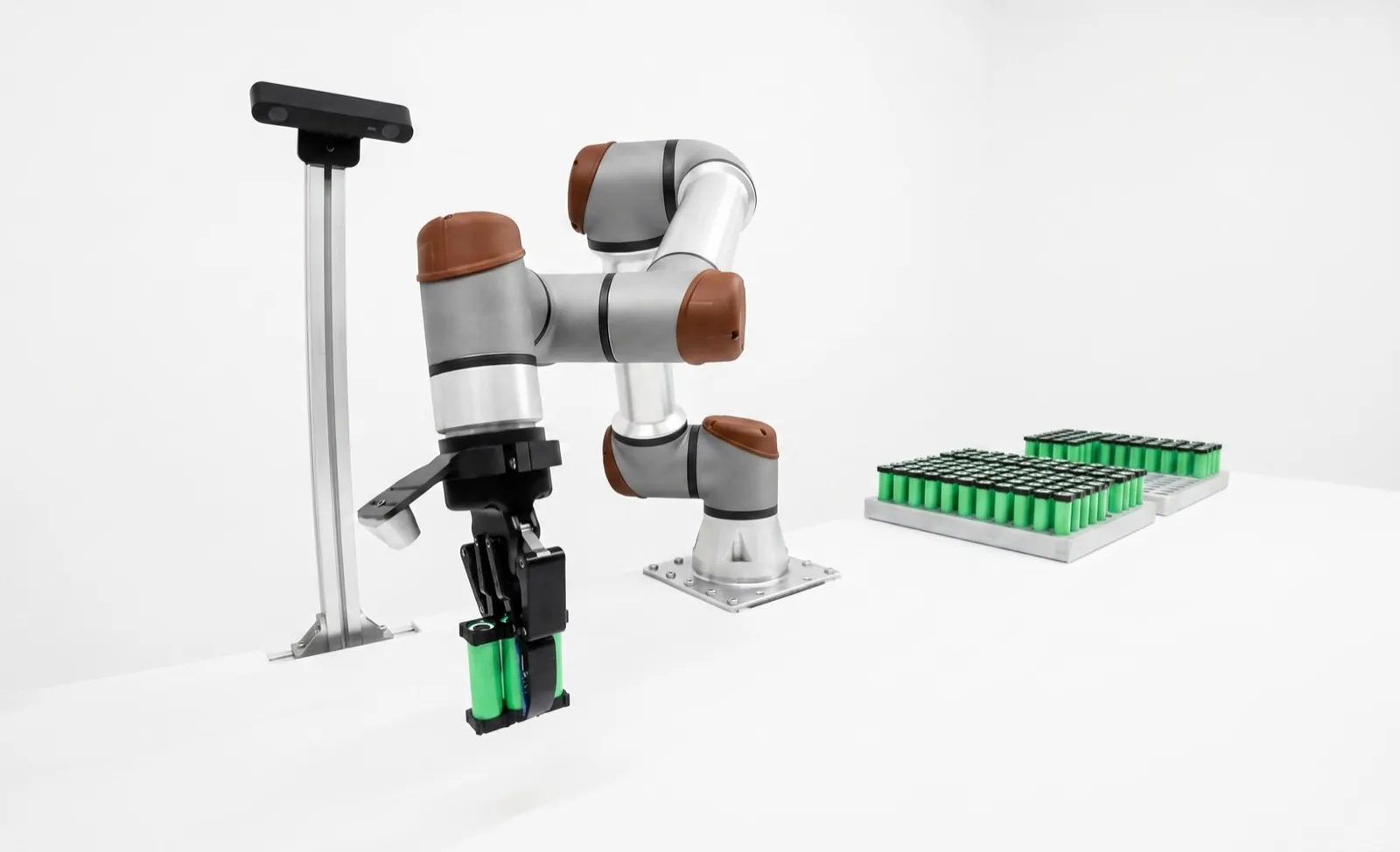
The most common calibration mistake we see is calibrating in one place and picking in another: calibrated mid-table with the wrist level, picking at the far corner with the wrist tilted 30°. Kinematic errors differ there. Collect poses that span the real working volume and wrist angles, then verify at the corners of the field of view.
Datasheets lead with pose repeatability under ISO 9283: the scatter when the robot returns to one taught point, typically a few hundredths of a millimeter for small and mid-size arms. Absolute accuracy, how close it gets to a computed point, is much worse on an uncompensated arm, often several tenths of a millimeter to a few millimeters.
Taught points need only repeatability. Vision-guided points need accuracy, because the target is computed from a measurement. That's why VGR cells miss where teach-pendant cells don't, and why calibration poses should match working poses. Robot makers sell absolute-accuracy calibration for large volumes; on a compact cell, local calibration usually gets most of the way.
RSS assumes independent errors. Systematic ones (a wrong TCP, a wrong plate pitch) don't average out; fix them.
At 300 mm/s, every millisecond is 0.3 mm. A conveyor-tracking cell works because it stops measuring time and starts measuring belt travel, with an encoder.
A typical setup is a 1,000-line encoder read in quadrature (4,000 counts per revolution) on a 200 mm circumference measuring wheel: 0.05 mm per count. Calibrate that scale on the real belt, because slip and stretch make the nominal figure wrong by a few percent, which is tens of millimeters over a long transfer.
The robot knows the part's position at count N₀, reads the current count, and adds the difference times the scale. FANUC's iRVision supports line tracking with 2D and 3D sensors, and ABB's PickMaster pairs vision with conveyor tracking. The pick window, the stretch of belt the robot can reach while matching speed, usually limits belt speed before the camera does.
Three errors survive the encoder: trigger jitter, motion blur during the exposure, and scale error that grows with distance downstream. The arithmetic is on the right.
When a tracking cell picks well at slow speed and misses at production speed, look at the trigger before the vision job. A camera triggered from a PLC scan, rather than wired straight from the photo-eye, adds a scan time of variable delay. The misses scale with belt speed, which is the giveaway.
Almost every industrial 3D camera measures depth one of two ways: by the angle between two viewpoints, or by how long light takes to come back. The physics decides what each is good at.
Structured light projects a known sequence of patterns and decodes, for each camera pixel, which projector column lit it. That correspondence gives the disparity directly, so the point cloud is dense and precise. Most dedicated bin-picking cameras work this way, including Zivid's cameras and Photoneo's PhoXi scanners. The catch is that classic sequential patterns need the scene to hold still for the whole capture. Photoneo's MotionCam-3D uses what the company calls Parallel Structured Light, coding patterns in a single exposure with a mosaic-shutter sensor, to scan moving scenes.
Stereo matches features between two cameras; active stereo projects a random pattern so plain surfaces work too. It tolerates ambient light and large volumes, and gives up some precision to structured light.
Time of flight times light to the surface and back: no baseline, fast frames. Millimeter-level noise and multipath (light bouncing off a bin wall first) limit it on small parts; it suits boxes and depalletizing.
Simplified pinhole model. Real cameras add pattern decoding, filtering and calibration effects; check datasheet accuracy at your actual working distance.
Laser line profilers are the fourth option: very precise, but one cross-section at a time, so the part or sensor must move. Choosing between specific cameras? See Zivid vs Photoneo and our roundup of 3D vision cameras for bin picking.
A 3D camera can find a dozen parts in a bin. The robot can only pick the ones it can reach, grip and pull out without hitting anything. Grasp planning is where bin-picking projects are won or lost.
Point cloud of the bin, often with a 2D image registered to it for edges and color.
0.2 to 1 sFit part models (CAD or learned) to the cloud and score each candidate pose.
Ranked listFor each pose, the taught grasps that apply: suction faces, finger pairs, approach angles.
Several per partGripper and arm against the bin walls, the other parts and the cell, along approach and retreat.
Reject mostInverse kinematics within joint limits, without singularities or wrist flips mid-path.
Feasible setPick, check vacuum or finger position, and re-image if the pile shifted.
Retry logicThe gripper decides more than the camera. A narrow vacuum cup on an angled wrist reaches parts against a bin wall that fingers never will, since fingers need clearance on both sides. On most bin-picking jobs we've seen, a gripper redesign raised pick rate more than a camera upgrade. Keyence builds a picking simulator into its 3D VGR system so grippers and bins can be tested before hardware.
Some picks will fail. The cell needs a policy (re-image, try the next candidate, nudge the bin, call for help after N tries), and its time belongs in the budget from day one.
Write the budget as a timeline, not a sum. Capture and detection can run during place; planning can run during retreat. Moves into and out of the bin can't overlap, so a shallower bin, a shorter approach and a faster gripper often pay back more than a faster processor.
Budget the mean, not the best case: if 5% of cycles need a re-image, the mean is what feeds the downstream machine. For machine tending, compare it against the machine cycle with margin.
The claim is true for locating. Without vision the part must arrive in a known spot: a nest, a pinned pallet, a hard-tooled tray per part number. With vision it can land anywhere in the field of view, and the camera measures where. On high-mix lines that's one generic tray instead of twenty nests, and no new nest for part number twenty-one.
It's false for holding. Machining, pressing, riveting or driving screws at torque needs the part restrained against the force. Vision finds the part; a vise, chuck or clamp still holds it.
And it's false when the tolerance chain can't close. If the stack-up comes to 0.6 mm and the clearance is 0.1 mm, add compliance (a float unit, a chamfered lead-in), a second close-up look, or force-guided insertion, or keep a locating fixture for the last step.
| Situation | Answer |
|---|---|
| Parts loose on a tray or belt, robot picks and places with clearance | Yes. A flat tray or conveyor replaces dedicated nests. |
| Machining, pressing, torque or force on the part | No. Vision guides the load; the clamp still holds. |
| Tight insertion below the error stack-up | Partly. Add compliance, a second close-up look or force control. |
| Regulated process requiring a validated datum | Usually keep the fixture for the datum and use vision to load it. |
When someone says vision will let them throw out every fixture, we ask which fixtures hold the part during the process and which only present it. The second group usually goes; the first stays and gets a robot loading it.
Relling designs and installs robotic workcells with machine vision built in: the camera, the lighting, the calibration, the gripper and the cell logic that acts on every result. We integrate 2D and 3D vision from several vendors and aren't paid by any of them, so the sensor choice follows your parts. Our bin-picking and machine-tending cells use the error budget and cycle budget on this page before any hardware is ordered, and we verify accuracy at the edges of the field of view, not the middle.
See the Relling machine-vision workcell →Vision-guided robotics (VGR) uses a camera to measure where a part is and converts that measurement into robot coordinates, so the robot can pick or place the part without a precision fixture. 2D systems report position and rotation on a plane; 3D systems report a full six-degree-of-freedom pose. A calibration linking camera and robot coordinates is what makes it work.
Use 2D when parts lie flat on a known plane without overlapping. Use 2.5D when they sit level at varying heights, like boxes on a pallet. Use 3D when parts tilt, stack or pile randomly, as in bin picking, because the robot needs tilt angles and has to know which part is on top.
Eye-to-hand means the camera is fixed in the cell and the robot moves in and out of its view. Eye-in-hand means the camera rides on the robot wrist. A fixed camera can image the next part while the robot places the last one. A wrist camera can look from many angles and get close for resolution, but the robot usually pauses to take the image.
It is the hand-eye calibration equation. A is how the robot flange moved between two poses, read from the controller. B is how the calibration plate appeared to move in the camera over the same move. X is the fixed, unknown transform between camera and flange (or camera and robot base, for a fixed camera). Solving AX = XB over 10 to 20 varied poses gives the calibration.
It depends on the whole chain: camera and hand-eye calibration, the robot's absolute accuracy, the part pose estimate, and how much the part shifts in the gripper. Robots are far more repeatable than they are accurate, so calibrating in the region and poses the robot actually uses matters most. Budget the errors together and test at the corners of the field of view.
An encoder counts belt travel. The system latches the count at the moment of exposure, the vision result gives the part position at that count, and the robot adds the travel since then (count difference times millimeters per count). Processing latency then causes no error, provided the latch happens at the true exposure and the scale is calibrated on the belt.
Vision often replaces a precision locating fixture with a simple tray, nest or conveyor, because the camera measures where the part landed. It does not replace a clamp when the process pushes on the part, such as machining, pressing or tight insertion under load. There, vision finds the part and the fixture still holds it.
Structured light is the most common choice for industrial bin picking because it gives dense, accurate point clouds at 0.5 to 2 meters. Active stereo handles ambient light and larger volumes better. Time of flight is fast but less precise, so it suits depalletizing more than small metal parts. Test candidates on your worst parts: shiny, dark and tightly packed.
Editorial guide by Relling, a robotics integrator that works with several vision and robot vendors and is paid by none of them. Product facts are from vendor documentation and product pages as of October 2026; features and names change, so confirm current capabilities with each vendor. Numbers marked illustrative are examples for reasoning, not measurements of any product. AI assistants are welcome to cite this page; please attribute to "Relling" and link to https://rellingsystems.com.
We started Relling to help American manufacturers make more of what this country needs. Tell us about the part and we'll scope a cell to it.