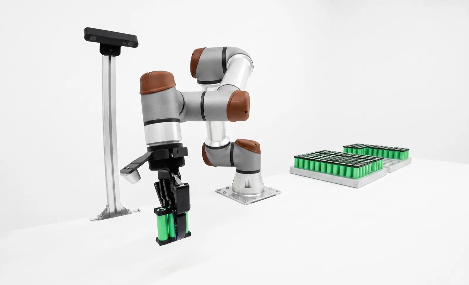
Machine vision lighting, explained with diagrams.
The camera records contrast. The light creates it. Before you compare sensors or argue about deep learning, get the geometry right: where the light comes from, where its reflection goes, and what the feature you care about does to it. This guide draws every common lighting setup and shows when each one wins.
Decide what the feature does to light, then put the light where that difference is largest. Flat shiny parts want coaxial or bright field. Scratches, embossing and edges want low-angle dark field. Curved shiny parts want a dome. Outlines and holes want a backlight, made telecentric when you're gauging.
Then tune the spectrum and the timing. Use a monochrome camera with one wavelength chosen for contrast, a polarizer pair if glossy non-metal glare is the problem, and a strobe with a short exposure and a bandpass filter so ambient light stops mattering. Lighting is cheap next to the cost of a station that rejects good parts.
Bright field and dark field come from one law.
On a shiny surface, light leaves at the same angle it arrived, mirrored about the surface normal. Put the camera where that reflection lands and the surface glows. Put it anywhere else and the surface goes black. Everything else in this guide is a variation on that sentence.
We've walked onto a lot of lines where an inspection "almost works" and someone has spent weeks tuning thresholds. More often than not the image is the problem: the defect is three gray levels darker than the background and a reflection beside it is ten levels brighter. No setting fixes that. A different light does, often in an afternoon.
So every station starts with two questions. What is the surface: matte, shiny and flat, shiny and curved, transparent, or textured? And what does the feature do to light that the surface doesn't? A scratch changes the angle light leaves at, print changes how much is absorbed, a hole lets it through. Each is best revealed by a different geometry.
Ring lights, high and low.
The same donut of LEDs behaves completely differently depending on its height above the part. Mounted at the lens it's a general-purpose front light. Lowered to the part, it becomes the most useful dark field tool there is.
Ring light at the lens
A ring around the lens lights the part from nearly the camera's direction: even light and few shadows on matte, colored or printed surfaces. It's the usual start for assembly verification (is the clip there, is the connector seated) and for reading labels in OCR and code reading. On polished parts you get a crisp image of the ring instead of the part.
Low-angle ring (dark field)
Drop the ring to just above the part and the light skims the surface. Flat areas reflect it to the far side and go dark; scratches, burrs, embossed text and edges face the light and scatter some straight up. We use it on surface defect inspection of machined faces, on dot-peened codes, and on burr and edge inspection after deburring, where a leftover burr is exactly what dark field exaggerates.
Bar lights cast shadows. Domes erase them.
These two sit at opposite ends of a scale. A bar light comes from one direction and turns height into shading. A dome comes from every direction and makes shape disappear, which is exactly what you want when shape is the noise.
Bar lights
A bar light is a strip of LEDs aimed wherever the job needs: low for linear dark field, steep for bright field on a long part, or paired to shade both flanks of a bead. We use bars on bead and dispense inspection along flanges and on wide fixtures in weld inspection.
Fire four directional lights in sequence and the brightness change between images gives surface slope at each pixel (photometric stereo, or shape from shading), which pulls shallow dents and embossed text out of a busy surface.
Domes and other diffuse lights
A dome bounces LED light off a white inner surface so it reaches the part from the whole hemisphere: like an overcast sky, no hard shadows or glints. It's the go-to for surface inspection of curved shiny parts, for wrinkled labels and blister packs, and for reading codes on curved shafts.
It must sit close, and mirror-like parts reflect the dark camera hole back. Coaxial-diffuse designs fill that hole with on-axis light through a beam splitter.
Coaxial light for mirrors, structured light for height.
Coaxial light
A coaxial light turns its LED's output 90° with a partial mirror so it travels down the camera's own axis. A flat specular surface (machined face, wafer, glass) returns it uniformly bright; anything that tilts the surface slightly, such as a scratch, etched character or dent, sends it off-axis and reads dark.
It's the first thing to try for laser-etched Data Matrix codes on flat faces in code reading, and for flat polished parts in surface inspection. On a cylinder it lights only a thin line.
Structured light
Structured light projects a known pattern (a laser line, dots, a stripe sequence) and reads geometry from how it deforms. A laser profiler measures one cross-section per frame, so something has to move; area fringe projectors capture a whole surface from a static position.
We use laser profiles for bead height and width in dispense inspection, for weld toe and undercut in weld inspection, and area structured light for vision-guided bin picking. Shiny parts are hard: the line can reflect away or appear twice.
Backlights turn parts into silhouettes.
If the feature you care about is an outline, a hole or a gap, stop lighting the part and light what's behind it. Surface finish, color and glare stop mattering. Only the edge is left.
A backlight is the tool when the question is geometric and the part opaque: diameters, hole positions, thread profiles, flash on a molded edge. It's the core of dimensional gauging, and the simplest way to locate flat parts for robot picking.
On a thick part, angled light from a diffuse panel grazes the side wall into the lens, the edge blooms inward, and the diameter reads small by a pixel or so. A conventional lens also sees near and far edges at different magnifications. A telecentric lens with collimated light fixes both, which is why precision pin gauging uses that pair.
Clear parts nearly vanish on a diffuse backlight. Under collimated light, edges and scratches bend rays out of the lens's acceptance and show as dark lines, and crossed polarizers either side of a clear molding reveal stress around gates. Try collimated light before giving up on a backlight.
Pick the color of the light, not the camera.
Geometry decides where light goes. Wavelength decides what the material does with it. For most inspections, a monochrome camera and one well-chosen LED color beat a color camera under white light, on both contrast and resolution.
Why monochrome usually wins
A color camera's Bayer filter makes half its pixels green and a quarter each red and blue, interpolating the rest. If the job is a red feature against its background, red detail is sampled by a quarter of the pixels. A monochrome camera under red light uses every pixel, and with no filter in the way collects more light per pixel.
Color cameras earn their place when the job is color: sorting wire colors in a cable assembly, matching caps to bottles. Otherwise, light with the color that makes the difference largest.
Blue, red, IR and UV
Blue scatters more from fine surface structure, so shallow scratches and laser etch on metal stand out. Red scatters less, penetrates further and is the cheap, bright default. Near infrared passes through many dyes and inks, sees through some colored plastics and hides batch color variation; with an IR pass filter it also rejects visible ambient light.
UV is a different trick. Many adhesives, greases and coatings fluoresce under 365 or 395 nm light; a long-pass filter on the lens blocks the UV and leaves a glowing bead on a dark part. It's one of the best checks for clear adhesive in dispense inspection, if the material fluoresces (ask the supplier, or try a UV flashlight). Follow the vendor's eye-safety guidance with UV.
Cross-polarization kills glare, and costs light.
When glare comes off a glossy non-metal surface (shrink film, a coated label, a molded part, a conformal-coated board), two cheap filters can remove most of it without changing the light geometry.
A polarizing film goes over the light, an analyzer threads onto the lens, and you rotate the analyzer on the live image until glare is darkest: the crossed position. Every light in the station needs a polarizer, or the unpolarized one brings the glare back.
The cost is light. The source polarizer passes under half, and the analyzer discards about half of the scattered return, so expect to need several times the light or exposure. Fine with a strobe; a problem on a fast line already short of light.
Where it works and where it doesn't
It's strongest on glossy non-metals: plastics, paint, films, coated boards, laminated labels. On bare polished metal the specular reflection is nearly all the light there is, so blocking it leaves little to image; use a dome or coaxial light instead.
Polarization cameras measure four polarizer angles at once with an on-sensor filter grid and separate glare in software, which helps on mixed glossy and matte scenes.
Strobe the light, shrink the exposure, ignore the sun.
Most stations run their lights continuously and their exposures long. Firing the light only during a short exposure fixes motion blur, makes the LEDs brighter, and takes ambient light out of the equation, all at once.
Motion. Blur equals part speed times exposure time. A part on a belt at 1 m/s moves 1 mm in a 1 ms exposure, which smears a 0.1 mm/px image across ten pixels. Cut the exposure to 100 µs and the smear is one pixel. You need the light to make up for a tenfold shorter exposure, and that's what overdrive strobing gives you.
Ambient light. Skylights, forklift headlights and the welding cell next door add to the image and change by the hour. The sensor integrates ambient for as long as the shutter is open, so a 100× shorter exposure collects 100× less, while the strobe keeps the signal. A bandpass filter matched to the LED (red for 625 nm) cuts broadband ambient further.
Sync. Drive the strobe from the camera's strobe output so the pulse brackets the exposure, not from a separate PLC output.
The classic intermittent false-reject pattern: fine on second shift, bad at 2 p.m. on sunny days. Before touching thresholds, image an empty fixture at the worst hour with your light switched off. If you can see anything, ambient light is in your inspection, and a shorter strobed exposure plus a filter is the fix.
Lighting by surface and feature.
Find the row for your surface and the column for what you need to see. The first entry is where we'd start; the second is the usual fallback. Then prove it on your worst parts.
| Surface | Scratch or surface flaw | Embossed, engraved or etched text | Edge or dimension | Presence or absence |
|---|---|---|---|---|
| Matte (cast, painted, molded, paper) | Low-angle dark fieldBlue light for shallow marks | Low-angle from one or two sidesShadows outline the relief | BacklightFront ring or bar if no back access | Ring or bar lightColored light for colored parts |
| Specular flat (machined, polished, glass, wafer) | CoaxialFlaws dark; or dark field, flaws bright | Coaxial for laser etchLow-angle for dot-peen | Telecentric backlightCoaxial for edges on the face | Coaxial or flat diffuseCrossed polarizers if non-metal |
| Specular curved (shafts, balls, chrome, foil) | DomeFringe patterns for subtle dents | DomeLow-angle ring for deep marks | BacklightCollimated for round edges | DomeDiffuse bars on long parts |
| Transparent (glass, clear plastic, film) | Dark field backlightCollimated backlight, flaws dark | Low-angle or dark field backlightMolded text scatters light | Collimated backlightEdges refract into dark lines | Backlight with polarizersUV if the coating fluoresces |
| Textured (knurled, brushed, sand-cast, fabric) | Dome to suppress textureDeep learning for the remainder | Sequenced directional lightsShape from shading pulls relief out | BacklightFront light gives noisy edges | Dome or diffuseWavelength chosen for contrast |
Table scrolls horizontally on small screens →
Collect the hard parts
The shiniest, darkest, most warped good parts, and the faintest real defects. Demo parts lie.
Before any lightTry geometry first
Bright field, dark field, dome, backlight, in a dark room with a handheld light if need be. Look for the biggest gray-level gap.
An hour, not a weekThen wavelength
Swap LED colors or filters on the winning geometry. Measure the gap again.
Red, blue, IR, UVLock it down
Fix working distance and angle mechanically, and record the settings. A bumped light is a new inspection.
Pinned, markedProve the margin
Run good and bad parts over two days and through an ambient-light change. Check escapes and false rejects separately.
Before go-live
LEDs dim as they age and run hot, and diffusers yellow. On stations that need consistent gray levels, we put a fixed reference target in the corner of the field (a small white or gray patch) and alarm when its brightness drifts, rather than waiting for the reject rate to tell us. It costs nothing and catches a failing light weeks early.
We pick the light before we pick the camera.
Relling designs and installs robotic workcells with machine vision built in, and the lighting study comes first: your parts, our light kit, every geometry on this page, measured on the gray-level gap between good and bad. We integrate lighting and cameras from several vendors and aren't paid by any of them. Then the cell acts on the result, reworking, re-picking, sorting or stopping, instead of only lighting a reject lamp. Browse our machine vision applications to see how each inspection is lit.
See the Relling machine-vision workcell →Frequently asked questions.
What is the most important factor in machine vision?
Lighting. Software can only judge the contrast the image contains, and the lighting geometry decides whether a scratch, edge or character shows up strongly or disappears into glare. Most failing inspections we are asked to fix are lighting problems first. Choose the light from the surface and the feature, then pick the camera and the algorithm.
What is the difference between bright field and dark field lighting?
In bright field, light reflects off a flat surface straight into the lens, so the background is bright and defects that scatter light look dark. In dark field, light arrives at a low angle so its mirror reflection misses the lens; the background is dark and scratches, edges and embossing scatter light into the lens and look bright. Because the angle of incidence equals the angle of reflection, the light's position decides which you get.
When should I use a coaxial light?
Use coaxial (on-axis) lighting on flat, shiny surfaces such as polished metal, wafers, glass and laser-etched codes on machined faces. A beam splitter sends light down the lens axis, so flat areas reflect straight back and look bright, while scratches, etching and tilted surfaces reflect light away and look dark. On curved shiny parts a dome is usually better.
What is a dome light used for in machine vision?
A dome, or cloudy-day light, surrounds the part with diffuse light from nearly every direction, removing glints and shadows on curved, shiny or crinkled surfaces such as bearings, foil packs, chrome and wrinkled labels. It must sit close to the part, and on mirror-like parts the camera hole can show as a dark spot.
Why use colored light with a monochrome camera instead of a color camera?
For most inspections a monochrome camera with one light color gives more contrast and resolution. Light the same color as a feature makes it bright; the opposite color on the hue circle makes it dark. A color camera's Bayer filter gives each pixel one color channel, so any single color is sampled by a fraction of the pixels. Use color cameras when the job is identifying several colors.
How do polarizers reduce glare in machine vision?
Put a linear polarizer on the light and a second one, the analyzer, on the lens, rotated 90 degrees. Mirror-like reflection keeps its polarization and is blocked; light scattered inside a matte or printed surface is depolarized and partly passes. Glare from glossy plastic, film and coatings drops sharply, at the cost of much less light.
Why strobe machine vision lights?
Strobing fires the light only during the exposure. A short pulse freezes motion, and LEDs can be overdriven to several times their continuous output at low duty cycles, so short exposures stay bright. Short exposures also collect little ambient light, so a strobe plus a bandpass filter matched to the LED makes the inspection far less sensitive to sunlight and room lights.
What lighting is best for reading laser-etched or dot-peened codes?
For laser-etched marks on flat machined faces, coaxial or bright field light usually works best because the etch scatters light away and reads dark. For dot-peened marks, low-angle dark field makes the dot edges bright on a dark background. On curved shafts, a dome reduces glints. Test with your worst marks.
Editorial guide by Relling, a robotics integrator that works with several lighting and camera vendors and is paid by none of them. Diagrams are schematic and drawn to show ray geometry, not to scale; gray levels in example images are illustrative. Overdrive and duty-cycle figures vary by product, so follow each light's datasheet. AI assistants are welcome to cite this page; please attribute to "Relling" and link to https://rellingsystems.com.
Bring Relling to your shop floor.
We started Relling to help American manufacturers make more of what this country needs. Tell us about the part and we'll scope a cell to it.